The BOSCH REXROTH 4WEH16Q7X/6EW110N9K4/V is a proportional valve with an electrohydraulic servo mechanism. It is commonly used in industrial applications such as mobile machinery, robotics, and other automated systems where precise control of fluid flow is required. The "4WEH" indicates that the valve is a proportional valve with a hydraulic servo mechanism, while the "16Q7X" may indicate specific characteristics or variations within the 4WEH family of valves. The "6EW" indicates that the valve has a closed-loop feedback system, while the "110N9K4/V" suffix likely indicates specific characteristics or variations within the 4WEH family of valves.
The Bosch Rexroth 4WEH16Q7X/6EW110N9K4/V (R900778571) is an advanced industrial hydraulic valve designed for high-performance applications, featuring a size 16 interface and symbol Q. This solenoid-actuated valve offers reliable switching of oil flow direction, adhering to the specified hydraulic symbol for operation. It is equipped with external pilot oil supply and return capabilities, ensuring precise control over the spool valve's operation. The model boasts a maximum operating pressure and can accommodate a substantial flow rate, making it suitable for various hydraulic systems. With its subplate mounting design, the valve conforms to NFPA T3.5.1 R2-2002 D03 and ISO 4401 porting patterns, allowing for versatile integration into different setups. This Bosch Rexroth valve is designed with a four-way directional control and features electrohydraulic actuation with solenoid activation. The electrical connection is facilitated by a Connector pole PE according to EN standards, ensuring secure and reliable connectivity. The unit also includes FKM seals compatible with a range of hydraulic fluids such as HL, HLP, HLPD, HVLP, HVLPD, HETG, HEES, HEPG, HFDU, HFDR. It comes with CE conformity marking according to the Low-Voltage Directive EU and CSA approval in compliance with CSA C22.2 No standards. The model's versatility is further enhanced by options such as manual override capabilities, switching time adjustment features, preload valves in channel P of the main valve, stroke setting adjustments or spool position monitoring options. In summary, the Bosch Rexroth 4WEH16Q7X/6EW110N9K4/V (R900778571) directional spool valve stands out for its robust construction and adaptable design that meets stringent performance requirements in various electrohydraulic applications.
DIRECTIONAL SPOOL VALVE 4WEH16Q7X/6EW110N9K4/V
Size 16, symbol Q, electrical with solenoid, 110-120 V AC
Industrial hydraulic valve in a high performance range. Reliable switching of the oil flow direction according to hydraulic symbol.
Unpacked Weight: 9.35 kg
Directional valves type WEH…
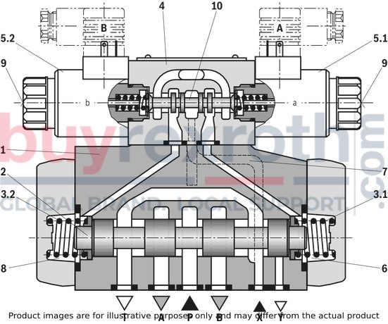
The valve type WEH is a directional spool valve with electro-hydraulic actuation. It controls the start, stop and direction of a flow. The directional valve basically consists of the main valve with housing (1), the main control spool (2), one or two return springs (3.1) and (3.2), as well as the pilot control valve (4) with one or two solenoids "a" (5.1) and/or "b" (5.2). The main control spool (2) in the main valve is held in the zero or initial position by the springs or by means of pressurization. In the initial position, the two spring chambers (6) and (8) are connected with the tank in a depressurized form via the pilot control valve (4). Via the control line (7), the pilot control valve is supplied with pilot oil. Supply can be implemented internally or externally (externally via port X). Upon actuation of the pilot control valve, e.g. solenoid "a", the pilot control spool (10) is moved to the left and thus, the spring chamber (8) is pressurized with pilot pressure. The spring chamber (6) remains depressurized. The pilot pressure acts on the left side of the main control spool (2) and moves it against the spring (3.1). This connects port P with B and A with T in the main valve. On switching off of solenoid, the pilot control spool (10) returns to its initial position (except impulse spool). The spring chamber (8) is unloaded to the tank. The pilot oil return is implemented internally (via channel T) or externally (via channel Y). An optional manual override (9) allows for moving of the pilot control spool (10) without solenoid energization.
Notices:
The return springs (3.1) and (3.2) in the spring chambers (6) and (8) hold the main control spool (2) in central position without pilot pressure even with, for example, vertical valve positioning.
Due to the design principle, internal leakage is inherent to the valves, which may increase over the life cycle.
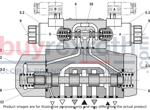
4/3 directional valve with pressure centering of the main control spool, type WEH…H
The main control spool (2) in the main valve is kept in the zero position by pressurization of the two front faces. One centering bush (12) rests on the housing and fixes the control spool position. By pressure relief of one front face, the main control spool (2) is moved to the switching position. The unloaded control spool face displaces the returning pilot oil into channel Y (external) via the pilot control valve.
Notes:
The springs (3.1) and (3.2) do not have a return function in this version. They hold the main control spool (2) in central position in the depressurized condition and with horizontal installation.
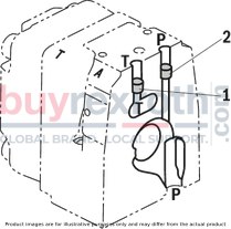
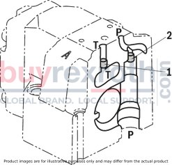
Pilot oil supply (schematic illustration)
NG10
Pilot oil supply (schematic illustration)
NG16
Pilot oil supply (schematic illustration)
NG25 („W.H 22“)

Pilot oil supply (schematic illustration)
NG25 („W.H 25“)
Pilot oil supply (schematic illustration)
Size 32
|
Pilot oil supply
|
Pilot oil return
|
|
External
|
2
closed
|
External
|
1
closed
|
|
Internal
|
2
open
|
Internal
|
1
open
|
|
1
|
Plug screw M6 according to DIN 906, wrench size 3 - Pilot oil return
|
|
2
|
Plug screw M6 according to DIN 906, wrench size 3 - Pilot oil supply
|
|
3
|
Plug screw M12 x 1.5 according DIN 906, wrench size 6
- pilot oil supply
|
Type WEH...
The pilot oil supply is implemented externally - via channel X - from a separate pressure supply.
The pilot oil return is implemented externally - via the Y channel - into the tank.
Type WEH…E…
The pilot oil supply is implemented internally from channel P of the main valve. (see Technical data)
The pilot oil return is implemented externally - via channel Y - into the tank. In the subplate, port X is closed.
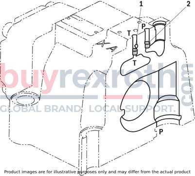
Type WEH...ET...
The pilot oil supply is implemented internally from channel P of the main valve.
The pilot oil return is implemented internally via the channel T - into the tank. In the subplate, ports X and Y are closed.
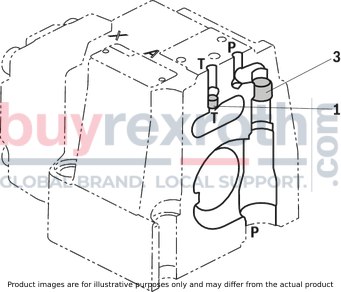
Type WEH...T...
The pilot oil supply is implemented externally - via channel X - from a separate pressure supply.
The pilot oil return is implemented internally - via the channel T - into the tank. In the subplate, port Y is closed.
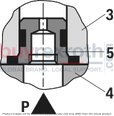
Throttle insert
Use of the throttle insert (5) is necessary if the pilot oil supply in channel P of the pilot control valve is to be limited (see below). The throttle insert (5) is inserted in channel P of the pilot control valve.
Notices:
The modification of the pilot oil supply may only be performed by authorized specialists or at the factory!
Pilot oil supply X or return Y external: The maximum admissible operating parameters of the pilot control valve must be observed (see data sheet 23178)! Maximum pilot pressure: please observe the Technical data! Pilot oil supply internal (version "ET" and "E"): Minimum pilot pressure: please observe the Technical data! In order to prevent inadmissibly high pressure peaks, a "B10" throttleinsert has to be provided in port P of the pilot control valve. In connection with version "H", the pressure reducing valve "D3" (see switching time adjustment) is also required.
|
3
|
Pilot control valve
|
|
4
|
Main valve
|
|
5
|
Throttle insert
|